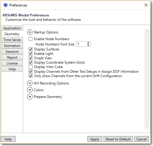
In this dialog the default behavior of the geometry windows can be specified.
Startup Options
Enable Node Numbers
Specifies if Node Numbers should be displayed by default or not. By default this option is unchecked. At runtime, the user can also choose to Show/Hide the Node Numbers from the Geometry Window Properties (link to geometry properties)
Display Surfaces
Specifies if Surfaces of the 3D objects should be displayed by default or not. By default this option is checked. At runtime, the user can also choose to Show/Hide the Surfaces from the Geometry Window Properties
Enable Light
Specifies if Light should be applied on the 3D objects by default or not. By default this option is checked. At runtime, the user can also choose to Enable/Disable the Surfaces from the Geometry Window Properties
Single View
In case this option is checked, at geometry Window startup, a Single View is displayed i.e. only the main view which can be rotated, panned, resized.
In case this option is unchecked then at Geometry Window startup, a Quad View is displayed displaying the same 3D object from 4 different perspectives.
Display Coordinate System Axis
Specifies the default behavior for displaying axis along with the 3D objects for easier understanding of the 3D space.
Display View Cube
Specifies the default behavior for displaying View Cube along with the 3D objects for easier manipulation with operations in 3D space like rotation, going to specific perspective, panning.
Display Channels from Other Test Setups in Assign DOF Information
When the Assign DOF Information Task is active, the user can see the channels from the other test setups, making it easier to see which nodes are not yet associated with the sensors. The color of these channels can be configured in the Colors section below.
Only show Channels from the current Drift Configuration
When selected this option will present only the channels for the current drift configuration.
Note: Try to limit all of these options to the minimum required in order to have a clear overview of the 3D object and also to avoid performance loss.
AVI Recording Options
The AVI Recording can be used to create an AVI movie of the animation. The following options can be used to customize the capturing.
Compress AVI Video - By default this options is checked which means that the captured AVI movie will be compressed and therefore smaller in size. Un Checking this option may improve the quality of the video, but will also increase in size.
Show AVI Video Compressor Options is for users with more advanced knowledge. There are several types of compressor options which also depend on the installed video compressor code. It is recommended that this option remains unchecked unless you have some specific requirements.
Default Output Directory allows the user to specify a directory in which the captured AVI files will be stored. This can be useful, so that the user can specify a centralized location and does not have to take care of the location of each created file.
Default AVI file Prefix can be specified so when the AVI is saved, this predefined prefix will be already set in the filename. When saving the files you can always remove or change this prefix, but it may be useful to specify a prefix, so that you can easily distinguish the files.
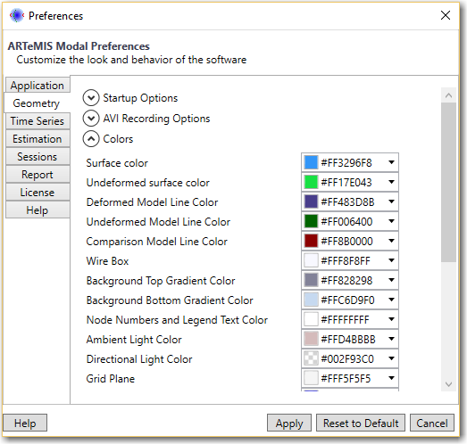
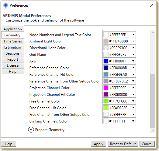
Colors
These preferences can be used to completely customize the 3D objects and 3D space displayed in the Geometry Window.
All of these preferences are affecting the Geometry Window immediately, so the best approach to customize this window is to first activate the Geometry Window and then go to these Colors preferences. Modify the colors of each item and observe the change in the Geometry Window.
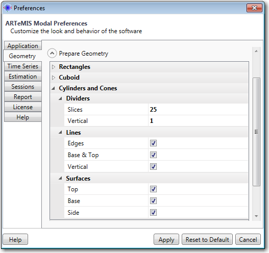
Prepare Geometry
This section configured the default (initial) state of the predefined objects which can be added in the Prepare geometry task. This can speed up the drawing of the geometry and avoid additional user interaction for re-defining some of the settings. These settings affect only new predefined objects which will be created. If necessary, the user can still customize each predefined object separately in the Prepare Geometry task.
Rectangles
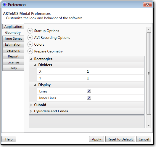
This section defines how many dividers should the Rectangle which is drawn in the Prepare geometry task have and if lines should be created or not.